Object detail screen: 3D visualization overlay
8.1.1 Object detail screen: 3D visualization overlay
Clicking on the tile of an individual .stl file or OBJ file listed inthe “FILES” pane towards the bottom of the object detail screen(refer again to Figure 8.4) will bring up a 3D visualization androtation interface overlay screen, at which you may “drag” thecomponent or object to rotate it in three dimensions; see Figure 8.6and Figure 8.7.
Figure 8.6: Worm Drive Gears Redux: 3D visualization of the base
Figure 8.7: Worm Drive Gears Redux: 3D visualization rotating the base
As an alternative to dragging and dropping the object itself onthe 3D visualization screen, you may click the “3D” icon (towardsthe upper right of the 3D visualization screen) to superimpose axesby which to manipulate the object’s location and orientation. InFigure 8.8, the “MOVE” axes are present, and as with the buildplate screen, clicking on an axis (or on the center “origin” ofthe object) will allow you to move the object along that axis(or move the object’s origin); Figure 8.9 shows the objectmoved.
Figure 8.8: Worm Drive Gears Redux: 3D visualization MOVE axes
Figure 8.9: Worm Drive Gears Redux: 3D visualization, object moved
Clicking the “ROTATE” button present at the bottom of the 3Dvisualization screen when “3D” axes have been selected, see Figure8.9, will switch from position axes to rotation axes; see Figure 8.10.(And similarly, once “ROTATE” axes have been selected, clicking the“MOVE” button will switch back to position axes.) Figure 8.11 showsthe object rotated around an axis.
Figure 8.10: Worm Drive Gears Redux: 3D visualization ROTATE axes
Relatively small rotations are often conveniently performed usingsimply the basic drag-and-drop of the object on the 3D visualizationoverlay screen. Larger rotations (such as arise, for instance, whendealing with OBJ file objects) are sometimes more convenientlyperformed using the “ROTATE” axes on the 3D visualization overlayscreen.
Figure 8.11: Worm Gears Drive Redux: 3D visualization screen, object rotated via axes
When “3D” axes have been enabled, click the “X” at the bottomof the 3D visualization screen (right of the “ROTATE” button) toremove the axes, and return to the basic 3D visualization overlayscreen.
Click the “X” at the upper right of the 3D visualizationscreen to close the overlay and return to the main object detailscreen.
Experimenting with rotating an object, or component of anobject, in three dimensions may help students (and you!) betterunderstand objects, and aid in developing spatial visualizationand mental rotation skills. In particular, experimenting withvisualizing such rotations may aid in determining a “good” printingorientation for an object – an orientation likely to result in a moresuccessful print, in which material can be “built up” from a base,limiting problematic protrusions, overhangs, or “bridging”during the printing, and reducing the need for printing supportmaterial.
Another use for the 3D visualization screen to rotate an object isto change the orientation of the model file image(s), particularly theprimary image, for one of your own objects.
At the object detail screen for one of your own objects,see Figure 8.12, click the object icon in the “FILES” pane tobring up the 3D visualization overlay screen, and rotate theobject as desired; see Figure 8.13. Note in Figure 8.13 thatthrough the overlay, you can see (faintly) the original objectorientation.
Figure 8.12: Velociraptor Business Card object detail screen
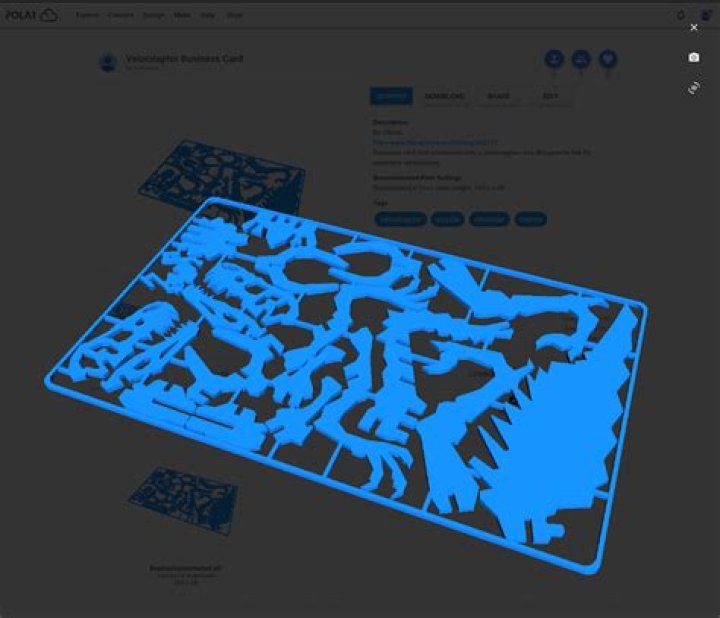
Figure 8.13: Velociraptor Business Card object: rotating image with 3D visualization overlay
When you have the object oriented as you would prefer, thenclick the camera icon towards the upper right of the 3D visualizationscreen. The main object image will be updated to use your selectedorientation; note in Figure 8.14 that through the overlay, you cannow see (faintly) that the orientation on the detail screen haschanged.
Figure 8.14: Velociraptor Business Card object: camera clicked on 3D visualization overlay
Click the “X” at the upper right of the 3D visualization overlayscreen to return to the object detail screen, which will now show thenew orientation for the object; see Figure 8.15. With this rotation ofthe object for the main image, note that the entire objectcan now be seen in the image (rather than, as before, havinga corner cropped off due to the perspective of the originalorientation).
Figure 8.15: Velociraptor Business Card object: detail screen updated
The camera icon is only present on the 3D visualization screenfor objects you own, so you may only change the main imageorientation for your own objects. You may, however, use the3D visualization overlay screen to experiment with viewingrotated orientations of the objects of others – as in Figure8.7.