PRINT SETTINGS and the slicing profile
10.2.2 The build plate screen: PRINT SETTINGS and the slicingprofile
On the build plate screen, clicking the “PRINT SETTINGS” tab in theright-hand pane (lower pane on narrow displays) gives access toslicing profile settings (also referred to as slicer configurationsettings). What makes for a good slicing profile depends upon themake of 3D printer in use, the type of filament in use, thecharacteristics of the object being printed, and its intendeduse.
You may choose between already defined slicing profiles byclicking on the current slicing profile (boxed name underneath“PRINT SETTINGS”) and then making your selection at the “SELECT SLICER CONFIG” pop-up screen; see Figure 10.8 and Section10.2.2.1.
Or, rather than using a predefined slicing profile as-is, youmay choose to fine-tune it to better align with the filamentin use, or your object or its intended purpose, via the threecategories (and corresponding screens) of settings underneath“PRINT SETTINGS”: “BASIC” settings, “ADVANCED” settings, or“G-CODE”. Note that the “BASIC” and “ADVANCED” settings havebrief online help text available: hover your cursor over thecircled “?” icon to the left of a setting to view a summary of itsmeaning.
If you use a predefined slicing profile and merely change somesettings, such changes only apply to the print job you create fromthis build plate screen (when you eventually press the “PRINT”button). However, if you are going to wish to use such a slicingprofile again later, on other objects – perhaps because you have adifferent type of filament that you’ll be using for multiple objects, orif you have an entire set of objects to print that will benefitfrom some special slicing profile – then you likely will wish tocreate and save your own custom slicing profile; see Section10.2.2.1.
Note that DREMEL 3D45 printers, which are quite automated,by default do not allow Polar Cloud “PRINT SETTINGS” to overrideall the printer’s internal settings; only if you configure yourDREMEL 3D45 printer to allow the Polar Cloud to override printerinternal settings will Polar Cloud slicing profile selection or certain“PRINT SETTINGS” adjustments be fully honored. See the Dremel3D45: Connecting to the Polar Cloud guide.
10.2.2.1 The build plate screen: slicing profiles
The name of the currently selected slicing profile is displayed in abox below “PRINT SETTINGS”; see Figure 10.7. Clicking on theslicing profile box will bring up a “SELECT SLICER CONFIG” screenat which you may select among already defined slicing profiles; seeFigure 10.8.
For the Polar3D printer in particular, the Polar Cloud providestwo predefined slicing profiles:
- “Polar3D 2.0 - PLA - 0.32mm - Draft Quality”
- “Polar3D 2.0 - PLA - 0.20mm - Medium Quality”
These two profiles for Polar3D printers differ in “Layer Thickness” (under “BASIC” settings: 0.32 mm vs. 0.2 mm), withthinner layers giving a more precise, refined quality to printedobjects, and also differ in “Top Layer Count” (under “ADVANCED”settings: 4 vs. 5), using more top layers when the layers arethinner.
For the FlashForge Inventor II printer, there are similarly twopredefined slicing profiles:
- “PLA - 0.30mm - Draft Quality”
- “PLA - 0.20mm - Medium Quality”
These two profiles for FlashForge Inventor II printers again differin the fundamental setting of “Layer Thickness” (under“BASIC” settings: 0.30 mm vs. 0.2 mm), as well as in “Top LayerCount” (under “ADVANCED” settings: 4 vs. 5) and “InitialLayer Thickness” (under “ADVANCED” settings: 0.30 mmvs. 0.20 mm), but also differ in a number of speed-relatedsettings, using slower speeds for the “Medium Quality” slicingprofile.
For DREMEL 3D45 printers, not only are PLA filament slicingprofiles predefined, but also slicing profiles for nylon filament and forABS filament are defined. However, DREMEL 3D45 printers arequite automated and by default use certain printer internal settings,overriding certain settings from a Polar Cloud selected slicingprofile; only if you configure your DREMEL 3D45 printer toallow the Polar Cloud to override printer internal settingswill Polar Cloud slicing profile selection (and certain “PRINTSETTINGS” adjustments, in particular temperature settings) be fullyhonored. See the Dremel 3D45: Connecting to the Polar Cloudguide.
Note that different makes of printers generally will have differentpredefined slicing profiles.
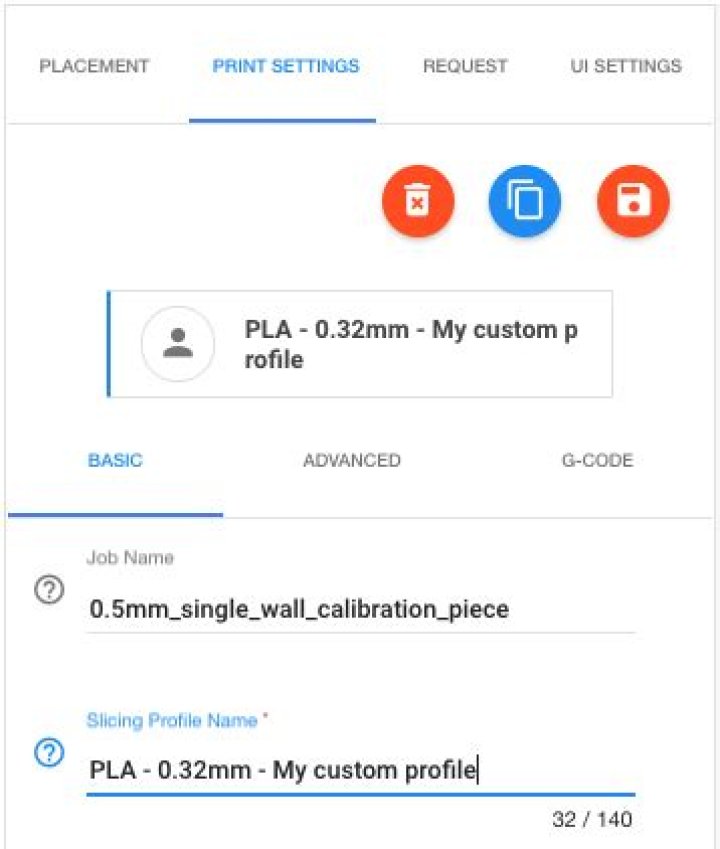
To generate a custom slicing profile, first duplicate one of thealready defined slicing profiles via the “Duplicate slicingconfig” button (the middle button directly underneath “PRINTSETTINGS”; see Figure 10.16). Give your custom slicing profile an appropriate name, using the “Slicing Profile Name”fieldunder “BASIC” settings; see Figure 10.16. Then make your desiredadditional adjustments to the slicing profile via the “BASIC”,“ADVANCED”, and “G-CODE” screens. Once your slicing profile iscomplete, save it by clicking the “Save config” button (therightmost of the three buttons directly underneath “PRINTSETTINGS”).
Figure 10.16: Polar Cloud PRINTSETTINGS custom slicing profile
Once you have generated and saved a custom slicing profile, itwill be available to you as a choice on the “SELECT SLICER CONFIG”pop-up screen whenever you are using the build plate screen; that is,your custom slicing profile will be available for your use onother objects. You may delete your custom slicing profile,should you wish, via the “Delete slicing config” button(leftmost button directly underneath “PRINT SETTINGS”): deletingyour custom slicing profile means that it will no longer beavailable as a “SELECT SLICER CONFIG” choice for any of yourobjects.
Note that should you wish, as well as downloading the.stl file(s) for your object, you may also download the slicingconfiguration you used (your job’s “PRINT SETTINGS”) via the“Download Config File” tab on a print job menu, whetherthe print job is viewed from a printer queue, from printer“HISTORY”, or from your account. Downloading a copy of the slicingconfiguration may be useful if you intend to recreate the objecton a printer not in the Polar Cloud, but which would use asimilar slicing profile. Comparing slicing configurations may alsobe very useful if you are trying to recall what you changedfrom one print to another that made a difference in print quality (especially if you didn’t at the time add any “COMMENTS”regarding the change to your print job)! However, the Polar Clouddoes not permit you to upload a slicing profile: instead, youmust always start with a Polar Cloud slicing profile and thenmodify that profile. (This is because for a successful print, it iscritical that a slicing profile be well-matched to the actualprinter in use: a slicing profile from some arbitrary externalsource is all too likely to be unsuitable for a Polar Cloud printjob!)
When you “Download Config File”, the slicing configuration issaved in a text file, with one setting per line; see for instance Figure10.17 which shows the top of two downloaded slicing configurationfiles differing in their settings of “Filament Diameter” (1.69 mmvs. 1.70 mm, respectively – so these were print jobs adjusting forusing a filament of slightly less than the standard 1.75 mmdiameter).
Figure 10.17: Excerpts of two Download Config File files differing inFilament Diameter
10.2.2.2 The build plate screen: PRINT SETTINGS BASIC
The “BASIC” settings under “PRINT SETTINGS”, see Figure 10.9,include:
- Job Name – the name of the print job to be created, for display on the print job tile. This defaults to the name of the object file (without its file extension), or the name of the first object file in the case of multi-component objects.
- Slicing Profile Name – the name of the slicing profile in use (or which you are newly defining; see the “Duplicate slicing config” button discussed in Section 10.2.2.1). The current slicing profile sets default values for many of the “PRINT SETTINGS”; to select an entirely different slicing profile, click the boxed name under “PRINT SETTINGS” to see a menu of already defined slicing profiles. (You may then fine-tune specific “PRINT SETTINGS” values for the print job you’ll be submitting.) Only enter a new or different name here if you are creating a new slicing profile.
- Temperature – the temperature to which the extruder should be heated. This operational value should always be set as appropriate for the type of filament you will be using, possibly modified by the type of printer; 185°C is appropriate for Polar 3D filament on a Polar3D printer. The proper temperature to set is an operational temperature (the temperature which the printer will measure and believe it has attained), which note may not be necessarily the exact same extrusion temperature that the filament manufacturer recommends for their filament. (Note also that the DREMEL 3D45 printer by default does not honor the Polar Cloud’s temperature settings, instead using its own internal settings. See the Dremel 3D45: Connecting to the Polar Cloud guide for details on how to configure the DREMEL 3D45 printer to honor Polar Cloud “PRINT SETTINGS” including temperature.)
- Platform Temperature – the temperature to which the platform bed should be heated; note that this setting is only available and displayed for printers which have a heated bed feature. (Note that the DREMEL 3D45 printer by default does not honor the Polar Cloud’s temperature settings, instead using its own internal settings. See the Dremel 3D45: Connecting to the Polar Cloud guide for details on how to configure the DREMEL 3D45 printer to honor Polar Cloud “PRINT SETTINGS” including temperature.)
- Layer Thickness – the thickness of each individual layer that the extruder will extrude. (Note that generally, “Layer Thickness” should be kept 20% or more smaller than “Nozzle Diameter” so that successive layers of extruded material are pressed together, rather than barely touching or just resting on each other.) Naturally, thicker layers allow printing an object more quickly, but with coarser quality; thinner layers mean more individual layers will need to be extruded, hence taking more time but resulting in a finer quality print (smoother surfaces, and better resolution of fine details). Thicker layers may also be helpful when printing objects with protrusions or bridges over voids, when a thinner layer may be more likely to droop or break. Layer thickness can be thought of as the resolution of your print. Other than overall object size, layer thickness will have the biggest impact on the print time for an object.
- Print Speed – how fast the extruder will move while extruding perimeter material. (Note that other speed settings, controlling speed while extruding the outermost wall of the object, controlling speed while extruding material in the interior of the object, controlling speed while printing the initial layer of the object, and controlling speed of moves when not extruding material, are available under “ADVANCED” settings. If you choose to print your object on a raft, additional speed settings relating not to the printing of the object itself but rather to the printing of the raft are available under “Raft Settings”.) While printing faster saves time, faster speed can result in blurred details. Your choice of “Layer Thickness”, as well as the type of filament and printer you are using, may also influence how fast it is wise to print.
- Filament Diameter – the diameter of the filament you are using. Always measure your filament diameter precisely, using calipers, and then make sure to set this value to correspond to your exact filament diameter! The Polar3D printer is designed (its extruder nozzle is designed) to operate on 1.75 mm filament, which is a standard filament diameter. But some filament manufacturer’s filament diameter will vary a bit – always check the actual diameter on a new roll of filament!
- Support – you may choose to extrude extra material, not part of your object itself, to aid in “supporting” your object as it prints.
- Support Type – if your object is not actually touching the build plate (in particular, if it does not have a flat bottom surface resting on the build plate), or if the object has large overhanging areas, you may wish to add support. The choices are:
- “None”
- “Touching Build Plate” – generate support between the build plate and the “bottom” of the object, filling in open volumes underneath the object per se; this is the default for most printers’ predefined slicing profiles.
- “Everywhere” – generate support also inside internal open volumes.
For a “Support Type” of “Touching Build Plate” or “Everywhere”, the gear icon to the right of that selected “Support Type” will bring up a “Support Settings” pop-up screen allowing adjusting when/what sort/and how much support that will be generated; see Figure 10.18.
Figure 10.18: Polar Cloud PRINT SETTINGS: Support Settings
- “Support Lines” may be set to either “Lines” or “Grid” as the pattern in which to print support material. Note that a grid checkerboard will provide stronger support than lines, but will likely be harder to remove.
- “Support Angle” specifies the minimum overhang angle, that is, angle between vertical and the object exterior, at which to begin generating support, so 0∘ means any overhang is supported, while 90∘ means support is never generated. The Polar3D, FlashForge, and DREMEL printers’ predefined slicing profiles set a “Support Angle” of 60∘, which is allowing an “arching bridge” type of overhang to print without support; some objects may need support sooner, and hence a “Support Angle” more like 45∘.
- “Support XY Distance” specifies the horizontal gap between the object itself and the support material.
- “Support Z Distance” specifies the vertical gap between the object itself and the support material underneath it. Larger “Support XY Distance” and “Support Z Distance” mean that the support will be easier to break away from the object; but too large of a “Support XY Distance” can mean that small overhangs are not supported, while too large of a “Support Z Distance” can mean that the object is insufficiently supported so that object overhangs droop noticeably.
- “Support Line Distance” specifies the spacing between the printed lines of support material (whether simply “Lines”, or lines of a “Grid”).
- Platform Adhesion Type – choose nothing or a skirt, or a brim, or a raft. Clicking the gear icon (to the right) will bring up a pop-up screen with settings for the type of adhesion assistance you have selected.
- None (Skirt) – The Polar Cloud’s predefined slicing profiles for Polar3D, FlashForge, and DREMEL printers print a small skirt; clicking the gear icon when you have this default of “None (Skirt)” selected will bring up a “Skirt Settings” pop-up screen (see Figure 14.19) with the default skirt values; to truly get no platform adhesion aid, set these skirt values to 0. The “Distance” setting controls how far the skirt is printed from the perimeter of the object. Since one of the reasons for extruding a skirt is to get a good flow of melted filament started at the beginning of a print, the “Minimal Length” setting controls the minimum amount of material that the printer will extrude to make the skirt – enough skirt loops will be extruded to extrude this amount of material.
- Brim – click the gear icon (to the right) to bring up a “Brim Settings” pop-up menu, whose only item will be “Line Count” (how many lines enclosing the perimeter of the object to print to form the brim).
- Raft – click the gear icon (to the right) to bring up a “Raft Settings” pop-up screen with many additional settings.
- Margin – the additional distance the raft extends past the outer perimeter of your object.
- Line Spacing – the spacing between “support” lines for the raft. Smaller spacing means a stronger raft, but uses more filament.
- Base Line – How wide to print lines of “support” material for the raft.
- Base Thickness – raft thickness.
- Base Speed – speed for printing the support portion of the raft.
- Interface Line Spacing – the spacing between lines of the top layers of the raft platform (the interface between the raft, and the object).
- Interface Thickness – the thickness of the intermediate layers of the raft.
- Interface Line Width – the width of the intermediate layers of the raft. Setting this to match your extruder nozzle size is usually adequate.
- Fan Speed – speed at which to run the fan (if your printer has one) while printing the raft.
- Surface Layer Thickness – the thickness of the surface layer (portion upon which the object rests) of the raft.
- Surface Layer Line Width – the line width of the surface layer of the raft.
- Surface Line Spacing – the spacing between lines of the surface layer of the raft.
- Surface Layers – The number of layers forming the “platform” of the raft. If you use a wide “Surface Line Spacing”, you may wish to use more “Surface Layers”.
- Surface Speed – the speed for printing the surface layer of the raft.
- Air Gap – the gap (distance) between the raft and the print overall, where a larger gap makes the raft easier to remove from the object, but may result in a “fuzzier” bottom of the object.
- Air Gap Layer 0 – the first layer air gap, or the gap (distance) between the last layer of the raft and the first print layer of the object.
- Support Type – if your object is not actually touching the build plate (in particular, if it does not have a flat bottom surface resting on the build plate), or if the object has large overhanging areas, you may wish to add support. The choices are:
Note that “Temperature” and “Filament Diameter” are the twomost fundamental settings for successful prints: know where to findand set them! And “Layer Thickness” is a primary determinant ofthe level of fine detail vs overall time required for your print (andtends to be the primary differentiator between the “DraftQuality” and “Medium Quality”predefined slicing profiles provided for various makes ofprinter).
10.2.2.3 The build plate screen: PRINT SETTINGS ADVANCED
The “ADVANCED” settings under “PRINT SETTINGS” controladjustments relating to infill (the extrusion of material in theinterior of objects), fine-tuning of the quality of the exterior ofthe object, the width of the extruder nozzle on your printer,fine-tuning of the print speed at the start of the print job,retraction and Z hop (raising up the filament and print headduring non-extrusion moves), and cooling during printing,including:
- Fill – setttings relating to infill.
- Infill Speed – the speed when extruding material in the interior of the object. Note that since the interior of the object is not visible, usually it is not as critical that the interior infill print quite as smoothly, so for faster printing it is typical to use a faster “Infill Speed” than the “BASIC” “Print Speed” used for object exterior walls.
- Infill Overlap – this percentage value determines how much the infill lines overlap with the innermost wall (exterior of the object) printed line; more overlap tends to result in a tighter bond between the exterior walls and the infill material, but on the other hand “too much” overlap can result in surface blemishes if the infill lines “telegraph” through to the exterior. See also the “Quality” setting “Wall Thickness”, as you may need to be particularly careful not to overlap “too much” when the exterior “Wall Thickness” is small.
- Infill Amount – this percentage value determines how “solid” to print the interior of the object, hence it affects how much filament will be used and the final weight of the printed object.
- Filament Flow – a setting which adjusts for filament density variations between different types or brands of filament, and different extruder characteristics on different printers. Only fine-tune using small adjustments between prints.
- Retraction – pulling up filament during non-extrusion moves (and related settings).
- Amount – the amount by which to retract the filament up into the print head.
- Speed – the speed at which to perform the retraction of the filament: too quick a speed may “yank up” just-extruded filament, whereas very slow retraction simply wastes time.
- Minimal Distance – the minimal travel distance of a non-extrusion move which will trigger retraction; non-extrusion moves shorter than this will not result in retraction.
- Minimal Extrusion – the minimal amount of raw filament input into the extruder between retractions. Repeatedly moving a section of filament up and down in the extruder while barely extruding any of it is liable to cause problems, as the melting filament may start forming blobs, dripping onto the build plate, or no longer feeding smoothly in the extruder. The “Minimal Extrusion” value, by enforcing that the specified amount of filament must be input into the extruder between retractions, limits the back-and-forth of nearly-the-same sections of filament in the extruder. A larger retraction “Amount” may necessitate a larger retraction “Minimal Extrusion”.
- Z Hop – the amount by which to raise the extruder nozzle, (where for a Polar3D printer, the entire print head is raised).
- Enable Combing – control whether combing (moving only across prior infill areas, but without retraction) is enabled; rather than the extruder moving in a straight line to each next extrusion start point, the extruder may travel in curves (to stay within the perimeter of previously extruded material). Enabling combing may allow greater print speed (even though the extruder may travel farther, retraction need not be performed) and it may reduce “stringing” across voids, but at the cost of possible surface blemishes (marks where the non-retracted extruder or oozing filament brushed or “combed” previously printed material) for flat top surfaces.
- Nozzle – adjustments relating to the extruder nozzle width.
- Nozzle Diameter – the diameter of the extruder nozzle. (Not available for Polar3D printers.)
- Extrusion Width – the width of the “line” of melted filament to extrude; this should be set to at least the “Nozzle Diameter” value; generally a value between about 100-150% of “Nozzle Diameter” is reasonable.
- First Layer Extrusion Width – the width of the very first “line” of melted filament to extrude; to help aid good flow and adhesion for the first layer, this value is often set to be a bit bigger than the “Extrusion Width”, and in any case should always be set to be greater than the “Nozzle Diameter” value.
- Quality – the shells forming the exterior of the object, or what might instead be described as the thickness of the exterior of the print object.
- Initial Layer Thickness – the thickness of the initial layer; this is generally set to be a bit thicker than used for subsequent (normal) layers (compare with the “Layer Thickness” value under “BASIC” settings) in order to get a solid, firmly-adhering-to-the-build-plate, first layer.
- Wall Thickness – the number of shells to print as side exteriors of the object.
- Bottom Layer Count – the number of solid layers to print as the bottom exterior (bottom surface) of the object.
- Top Layer Count – the number of solid layers to print as the top exterior (top surface) of the object.
- Speed – additional speed settings beyond the simple extrusion speed setting under “BASIC” settings.
- Initial Speedup Layers – speed up from the “Initial Layer Speed” to normal print speed during the specified number of layers.
- Initial Layer Speed – speed with which to print the initial layer; note that printing the initial layer a little extra slowly (more slowly than the “BASIC” “Print Speed” setting) tends to be a good idea, to get a very good first layer and improve adhesion to the build plate.
- Exterior Wall Speed (or Initial 0 Speed in earlier versions) – the speed for printing the outermost wall (shell). This is an important speed setting, as it affects the printing of the outermost (and hence visible) layer of the object. Printing this outer shell a little more slowly (than the general “BASIC” “Print Speed”) tends to be a good idea as it may aid in getting a better looking print.
- Inner Wall Speed (or Initial X Speed in earlier versions) – the speed for printing the innermost layer of the exterior walls, i.e., the shell at the juncture between the outer surface layers, and the infill. As this shell will not be visible, its printing does not affect the appearance greatly, but this shell does help form the connection between the outer shells and the infill. Typically this speed will be set to a value in-between the “Infill Speed” and the “Exterior Wall Speed”.
- Move Speed – the speed during non-extrusion moves, which note can safely be distinctly faster than the “Print Speed” (or even the “Infill Speed”) used while extruding material.
- Cool
- Minimal Layer Time – minimum time from the start of a layer until the next layer can be started; this is to ensure that the prior layer has had time to cool sufficiently. This setting works by slowing down the print of the whole layer; for small objects, or objects with small “footprints” this may mean the hot extruder nozzle moving very slowly, continuing to heat the already extruded filament resulting in overly melting the material. Thus for small objects, or objects with small build plate “footprints”, a more satisfactory approach than increasing “Minimal Layer Time” may be to print multiple objects simultaneously; see Section 14.1.3. (Note that the “‘Cooling Minimal Feedrate” option limits how slowly the extruder will print; if non-zero, it overrides “Minimal Layer Time”. Note also that the “Cooling Head Lift” option, if enabled, somewhat helps by moving the hot extruder away from the object while waiting for “Minimal Layer Time” to elapse – but it may result in oozing and stringing of filament between the object and the extruder, so printing multiple small objects at once is often still the better approach.)
- Cooling Fan – enable or disable cooling fan operation; note that this is only relevant if your printer includes a cooling fan. If “Cooling Fan” is set to “Enabled”, then clicking on the gear icon to its right will open up a “Cooling Settings” menu with settings:
- Starting Layer Number – layers to print before the fan is turned on.
- Cooling Minimal Feedrate – the minimum speed at which the printer will print; if non-zero, this overrides “Minimal Layer Time”. That is, in order to achieve a requested “Minimal Layer Time”, the printer will normally slow down, extruding material extra slowly; however, the printer will only slow down to “Cooling Minimal Feedrate”, (as overly slow extrusion tends to cause its own set of problems), even if this means that the layer prints in less than “Minimal Layer Time”.
- Cooling Head Lift – if enabled, the print head and extruder will be moved away from the object if a layer is completed before “Minimal Layer Time” has elapsed: the extruder will be moved away and the printer will wait for the rest of “Minimal Layer Time” to elapse before returning to print the next layer. Enabling “Cooling Head Lift” thus avoids one of the problems of attempting to use “Minimal Layer Time”: namely, the potential for the hot extruder nozzle, during the “Minimal Layer Time” delay, to unintentionally further melt already extruded material. However, with “Cooling Head Lift” enabled so that the extruder is moved away from the object while any remaining “Minimal Layer Time” elapses, because the extruder remains hot, some filament may ooze out during the wait, resulting possibly in: “stringing” between the object and the extruder, “blobs” of oozed material when the extruder returns to the object to continue printing, and/or under-extrusion at the start of the next layer due to melted filament having oozed out of the melt chamber. Thus enabling “Cooling Head Lift” may well be worth trying if during “Minimal Layer Time” extrusion delays the hot extruder near the object is doing damage to the object’s prior layers by further melted extruded material; however, printing multiple small objects (to indirectly take more time, thus allow more cooling between layers, while keeping the printer productively busy printing additional objects) may yield still better results!
- Cooling Fan speed min – percentage of maximum possible fan speed at which the fan is run for regular layers (layers that take more than “Minimal Layer Time”). (Regular layers that are larger and naturally take longer to print may not need as much cooling as very quickly printing, “Minimal Layer Time” layers.) Note that while the software is perfectly willing to attempt to run the print cooling fan at low speeds/low power, some printers’ fan hardware may not operate well at much less than full speed/power. Whether lower values will work properly depends entirely upon your printer’s actual fan: but do watch out for problems of the print cooling fan running erratically or not running at all if you’ve set this value rather low. Also: A value of 100% is generally quite reasonable for PLA filament; for other types of filament more prone to shrinkage during cooling, such as ABS filament, lower values may make sense.
- Cooling Fan speed Max – the percentage of maximum possible fan speed at which the fan is run for layers that take less than “Minimal Layer Time”. (Layers taking only “Minimal Layer Time” or less are taking only a short time, so the cooling fan should be run at fairly high speed to get good cooling prior to extruding subsequent layers.)
10.2.2.4 The build plate screen: PRINT SETTINGS G-CODE
Advanced users may wish to adjust the actual starting and endingG-code that will be sent to the printer. Use the “G-CODE” tab toaccess:
- Start G-Code
- End G-Code
Different 3D printers use and support somewhat different variantsof G-code; an overview of G-code commands, as used by someprinters, can be found at:
Be cautious changing G-code! Access to the G-code is providedfor expert users, but it should seldom be necessary to makechanges to it. Be sure to check exactly what Gcode your 3Dprinter supports, and that you fully understand any changes youmake.