The build plate screen: PLACEMENT
10.2.1 The build plate screen: PLACEMENT
The “PLACEMENT” tab towards the top of the build plate screen’sright-hand pane (lower pane in narrow display mode) allowsadjusting object position on the build plate (“MOVE”), objectsize (“SCALE”), and object orientation on the build plate(“ROTATE”).
In the build plate screen’s left-hand pane (upper pane on narrowdisplays), the object(s) are schematically pictured on the buildplate; see Figure 10.5. Clicking on the image of an object in theleft-hand pane (upper pane on narrow displays), or alternativelyclicking “PLACEMENT” in the right-hand pane (lower pane on narrowdisplays) and then clicking the name of the object (in a box below“PLACEMENT), allows you to adjust the placement of that object; seeFigure 10.6.
The default “PLACEMENT” mode when you first go to the build plate screen is “MOVE” (see Figure 10.6). In the right-hand pane(lower pane on narrow displays), below “PLACEMENT” and its list of(boxed) object names, are the placement mode choices “MOVE”,“SCALE”, and “ROTATE”. You may switch between placement modesby clicking the mode name or, when hotkeys are enabled, bypressing the corresponding key: W for “MOVE”, E for “SCALE”, and Rfor “ROTATE”.
When “PLACEMENT” of an object is selected, three colored axesappear on the object image, (red for the x-axis, green for the y-axis,and blue for the z-axis); the exact display of the axes variesaccording to whether you have selected “MOVE” mode (arrow-headedaxes originating from the center of the object, Figure 10.6), “SCALE”mode (block-headed axes originating from the center of the object,Figure 10.14), or “ROTATE” mode (circumferences of the object,Figure 10.15).
To perform a “MOVE”, “SCALE”, or “ROTATE” of an object,(according to which mode you have selected under “PLACEMENT”),you may position your cursor in the left-hand pane (upper pane onnarrow displays) over an axis and then drag the object along thataxis (moving, scaling, or rotating, as selected); the selected axis willappear in yellow, as shown in Figure 10.10. If you position yourcursor over the object’s center (for “MOVE” or “SCALE”) so that thecenter is lighted in yellow, as shown in Figure 10.11, you may moveor scale the object along all axes at once; for “ROTATE” mode, ayellow, outer circumference allows rotation around an axisperpendicular to your view of the object. Alternatively, in theright-hand pane (lower pane on narrow displays) you may usethe axis slider, see Figure 10.12, or the numeric input for theaxis, see Figure 10.13, to move/scale/rotate along an axis. Tonumerically move/scale/rotate along an axis, you may either click the up or down arrows to move the value up or down,respectively, or you may type in a numeric value directly.
Thus in particular, when “MOVE” is selected, you may move yourobject by:
- 1.
- clicking on an axis in the left-hand pane (upper pane on narrow displays) and dragging the image of the object along that axis on the build plate (Figure 10.10),
Figure 10.10: Polar Cloud build plate: object MOVE, x-axis selected
- 2.
- clicking on the object origin (center) in the left-hand pane (upper pane on narrow displays) and dragging the image of the object anywhere on the build plate (Figure 10.11),
Figure 10.11: Polar Cloud build plate: object MOVE, object center selected
- 3.
- clicking on an axis slider in the right-hand pane (lower pane on narrow displays) and dragging the slider (Figure 10.12),
Figure 10.12: Polar Cloud build plate: object MOVE, x-axis slider
- 4.
- clicking on the numeric value for the axis in the right-hand pane (lower pane on narrow displays) and clicking the up or down indicator to increase or decrease the value (Figure 10.13), or
Figure 10.13: Polar Cloud build plate: object MOVE, x-axis numeric input
- 5.
- clicking on the numeric value for the axis in the right-hand pane (lower pane on narrow displays) and then typing in the desired value directly.
Tip for entering a negative location value numerically:
If you manually entirely delete a current location value,the build plate screen will assume a value of 0. So when youwish to enter a negative location value numerically, it may bemore convenient to type a numeric value and then cursorleft to add the negative sign after typing the numeric value.
Scaling the size of, or rotating the orientation of, an object worksanalogously to moving the position of an object: select the type ofplacement and then use the corresponding axes.
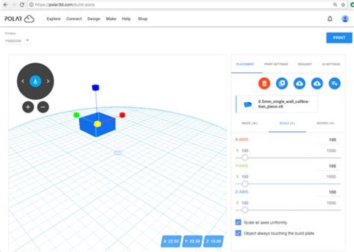
When “SCALE” is selected, see Figure 10.14, you may change thesize of the object via any of the “X-AXIS”, “Y-AXIS”, or “Z-AXIS”sliders under “SCALE” in the right-hand pane of the screen (lowerpane on narrow displays). Or you may click on an axis in theleft-hand pane (upper pane on narrow displays) and dragthe object’s size. Note the “Scale all axes uniformly”checkbox toward the lower right of the right-hand pane (lowerpane on narrow displays): this switch controls whether allaxes are scaled uniformly, vs. allowing stretching or shrinkingseparately along each axis. (Note that dragging on the yellowbox at the center of the object always scales uniformly on allaxes.)
Figure 10.14: Polar Cloud build plate SCALE object
When “ROTATE” is selected, see Figure 10.15, you may rotate theobject via the “X-AXIS”, “Y-AXIS”, and “Z-AXIS” sliders under“ROTATE” in the right hand pane of the screen (lower pane onnarrow displays). Or you may click on a circumference (coloredcircle) and rotate the object along the corresponding axis.In addition to the usual red x-axis, green y-axis, and bluez-axis being available, an outer yellow circumference allowsrotation about an axis perpendicular to your current view of theobject.
Figure 10.15: Polar Cloud build plate ROTATE object
Note that (unless hotkeys have been disabled under “UISETTINGS”) you may quickly switch between “MOVE”, “SCALE”, and“ROTATE” via theW, E, and R keys, respectively.
When moving, scaling, or rotating an object on the build plate,consider enabling the “Always show selected object’s boundingbox” control under “UI SETTINGS” to aid in detecting when theobject is getting near the edge of the build plate or near to anotherobject. Note that even when “Always show selected object’sbounding box” is not enabled, the bounding box will automaticallybe displayed in red (instead of its normal blue) to providewarning if you have moved, or scaled, or rotated an objectto a position/size/orientation in which it overhangs or is indangerof overhanging the edge of the build plate.
In addition to placement of the object itself, there is also a rotate view dial with two arrows (“Rotate camera left” and “Rotatecamera right”) around the outside, and a central, arrow-to-plate,“Place object on the build plate” button, plus below therotate view dial two circular buttons “+” (Zoom in) and “-”(Zoom out). (Note that the presence of the rotate view dialand zoom buttons may be disabled via the “Show camerahelper control” switch under “UI SETTINGS”.) The circular“+” and “-” buttons zoom in and zoom out, respectively,your view of the object, and the dial rotates your view of theobject. Compared to how “ROTATE” an object on the buildplate rotates the object’s placement on the build plate, therotate view dial rotates only your view of the build plate andobject – as if you moved your head or swivelled the build platearound.
You may also rotate your view of the build plate by pressing themouse and then dragging the build plate. While the “Rotatecamera left” and “Rotate camera right” arrows merely rotatethe build plate about the z-axis, note that dragging the build plateallows rotating through three dimensions – so in particular bydragging the build plate you may view the object from beneath or,conversely, from a “birds-eye” view directly above the build plate.And mouse or trackpad scrolling may be used to zoom the buildplate display.
Note that the “Place object on the build plate”(arrow-to-plate) button at the center of the rotate view dial does not perform a viewing operation; instead, it moves the object’splacement so that the object rests on the build plate.